Kuritakey M0110/A PCB Info Megapost *Updated*
Firmware
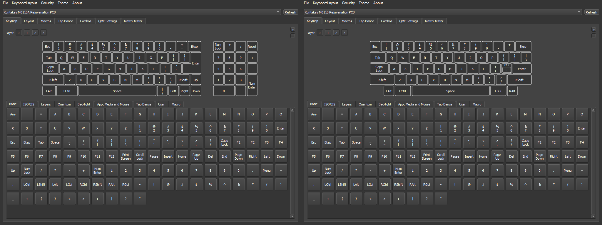
M0110 - Vial - to configure keymap you will need to download vial.
M0110A - Vial - FOR PRO MICRO ONLY - to configure keymap you will need to download vial.
Pi Pico MCU firmware coming shortly.
Assembly Instructions
Hi! Sorry for the delay on this, I got no-fault evicted and didn't (and still haven't) have time to build my copies of the production PCBs, which is what I was waiting on to provide detailed instructions. I've still got a lot of unpacking to do so I doubt I'm going to be able to update this with pictures from the final run for a while, but I can at least show you the general gist with the prototypes (not much has changed).
For all PCBs
Cable Making
On a 4p4c connector, the pinout goes something like this. I've labeled the pins on the connector, along with the PCB pins that connect to them:
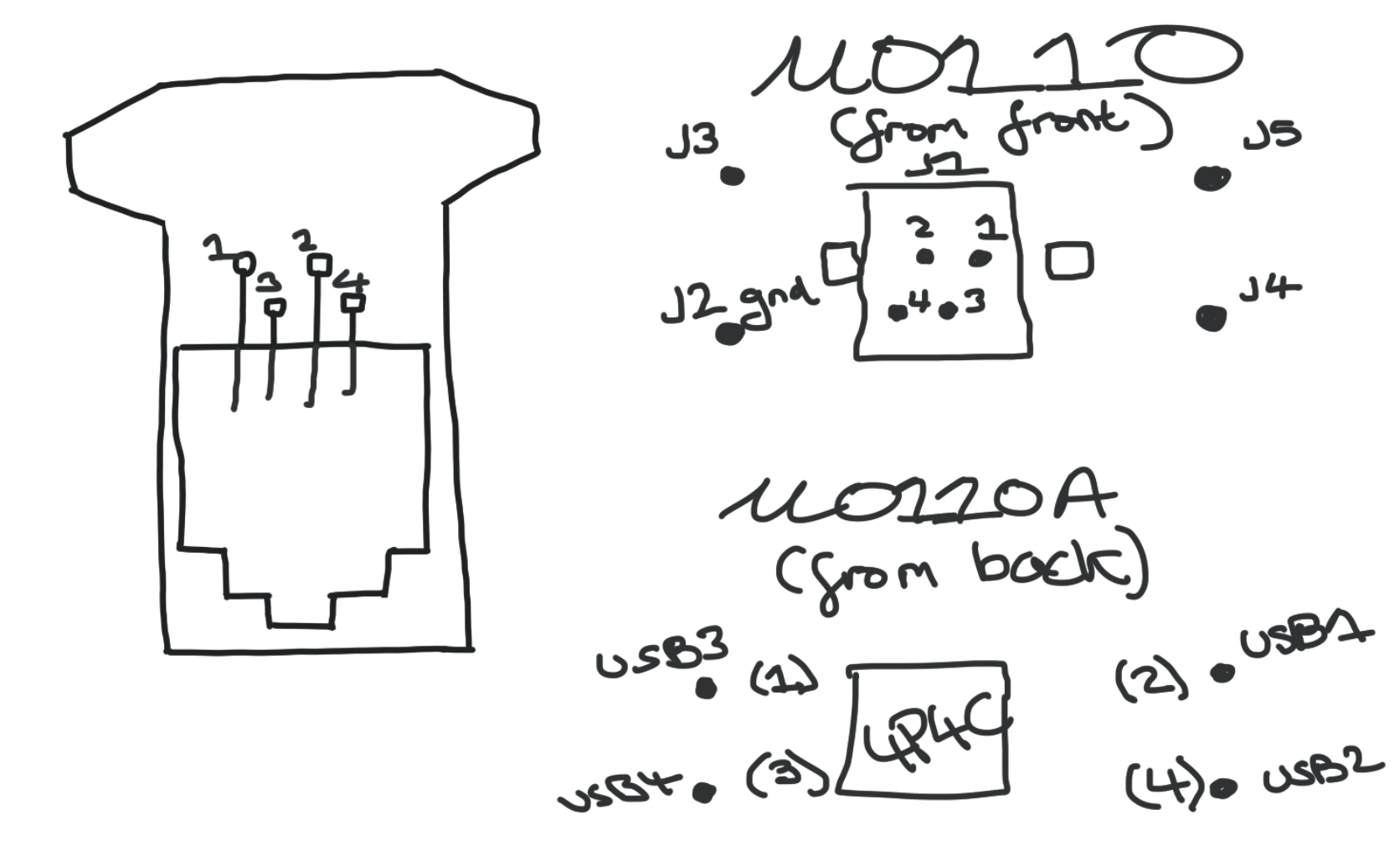
If you put your 4p4c socket into the PCB, and plug in your cable with one end cut off and the interior wires stripped, and multimeter each pin of the cable to each wire, you can figure out which interior wire colors correspond to which pin. I strongly recommend doing this method rather than trying to fly by eye, because crossover cables are quite annoying. But you can also figure this out by eye, just look at the colors of the cables through the connector and line them up with the pins on the socket. Write down the color to pin matchups.
You MUST use Pin 4 for USB ground (the black wire, goes to USB2 on M0110A and J2 on M0110) but beyond this you can match them up to the other wires in your USB cable however you'd like.
Cut the micro end off a micro USB cable with enough give to get you from the Pro Micro's port to the spots on the PCB. You'll either solder the individual wires into the USBX holes you choose on M0110A, or scroll down to the end for M0110 instructions.

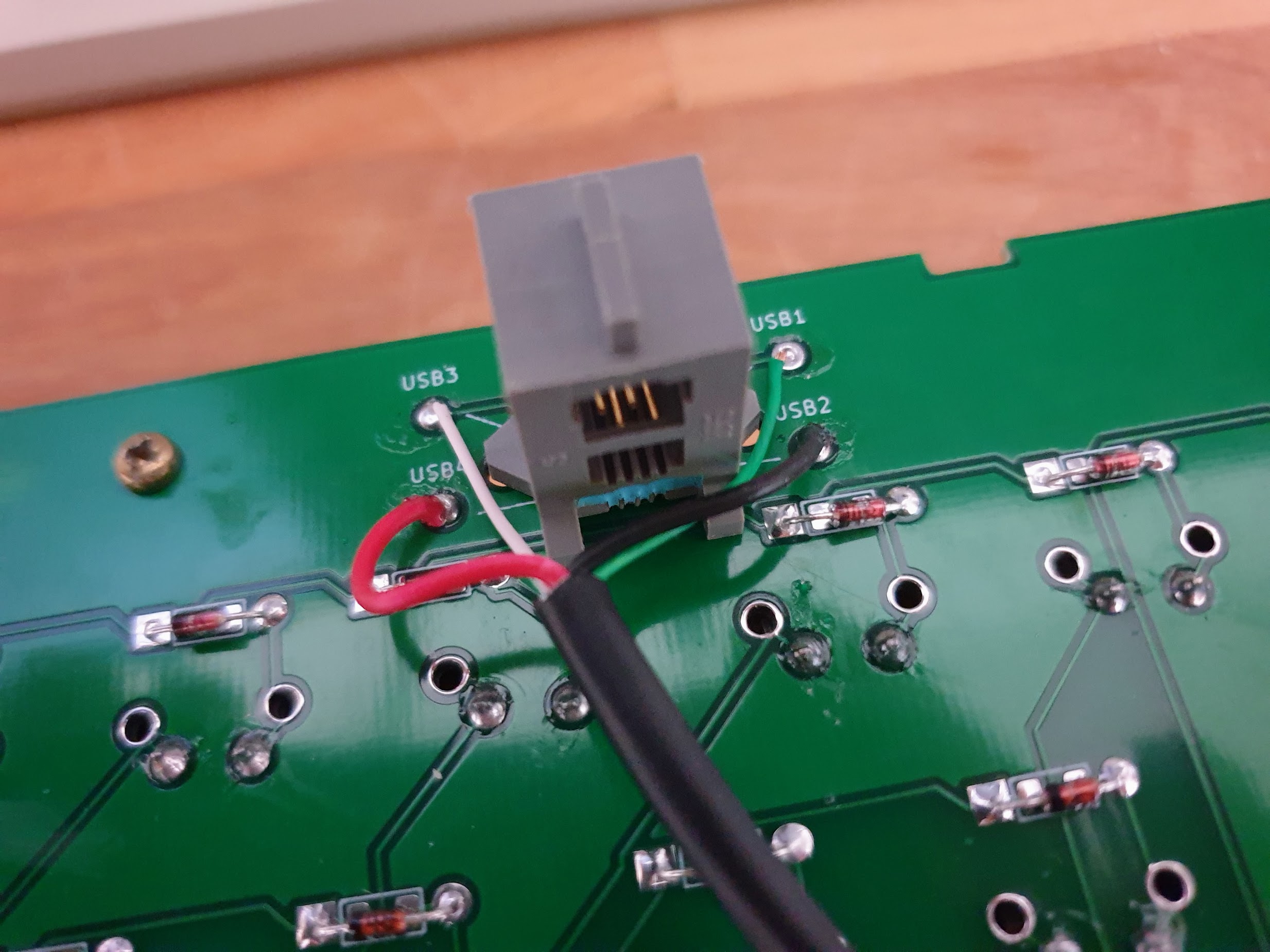
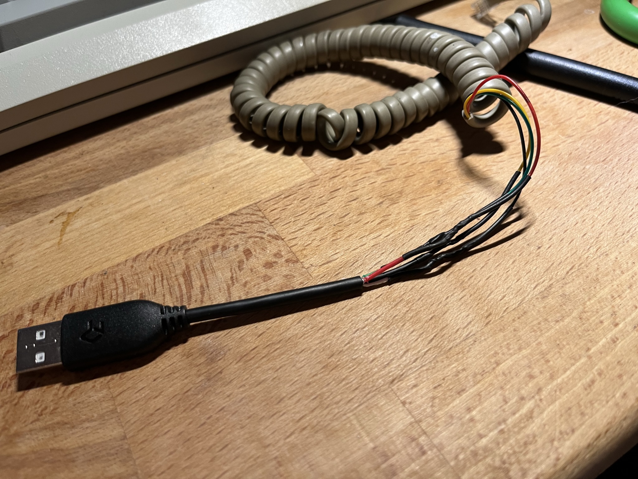
After this, look at the pin numbers to color associations you wrote down before, and add the USB wire colors to each pin (making sure Pin 4 is USB ground). Strip the USB-A end of the microUSB cable, giving yourself enough room to slide the big heatshrink over the whole thing and the little heatshrinks over each individual wire. Now strip all the interior wires on the 4p4c cable you're using. Splice the stranded wires together using your preferred technique (I do the linesman splice) and solder. Once you've soldered, leave it to cool for a couple seconds, slide the small heatshrink over the joint you just made, and heat it up. You should have something that looks like this:
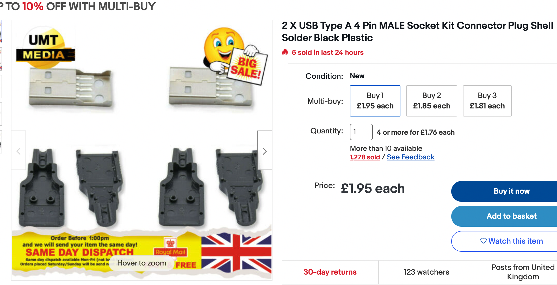
For those who are a little less confident with a soldering iron or wire splicing, I recommend buying something like this and referring to the USB-A cable pinout here.
Flash your Pro Micro with a regular cable first and then try plugging in the cable attached to the PCB and your new 4p4c-USB cable in the 4p4c port. If it works, great! If not, you'll need to recheck your wiring.
For M0110 Only
Follow all the cabling instructions as above. If you look at the first diagram on this post, you'll see the pinout for the loose pins of the 4p4c connector. As this is a one sided PCB, there's nowhere to solder the 4p4c connector in, so we'll have to get a little inventive. Thread your micro-end USB wires through the respective J holes on the non-solder side of the PCB (making sure to use J2 for the ground wire) and solder them down to the pads on the back of the PCB. Next, strip your kynar wires and solder one end to each of the solder joints you just made for the USB wires.
You'll see some small holes next to each J hole that have no pad on either side. These were added in the final production run to make it easier to route this kynar wire to the pins on the 4p4c connector. Thread your wires through these holes and then cut to size and strip the other end.
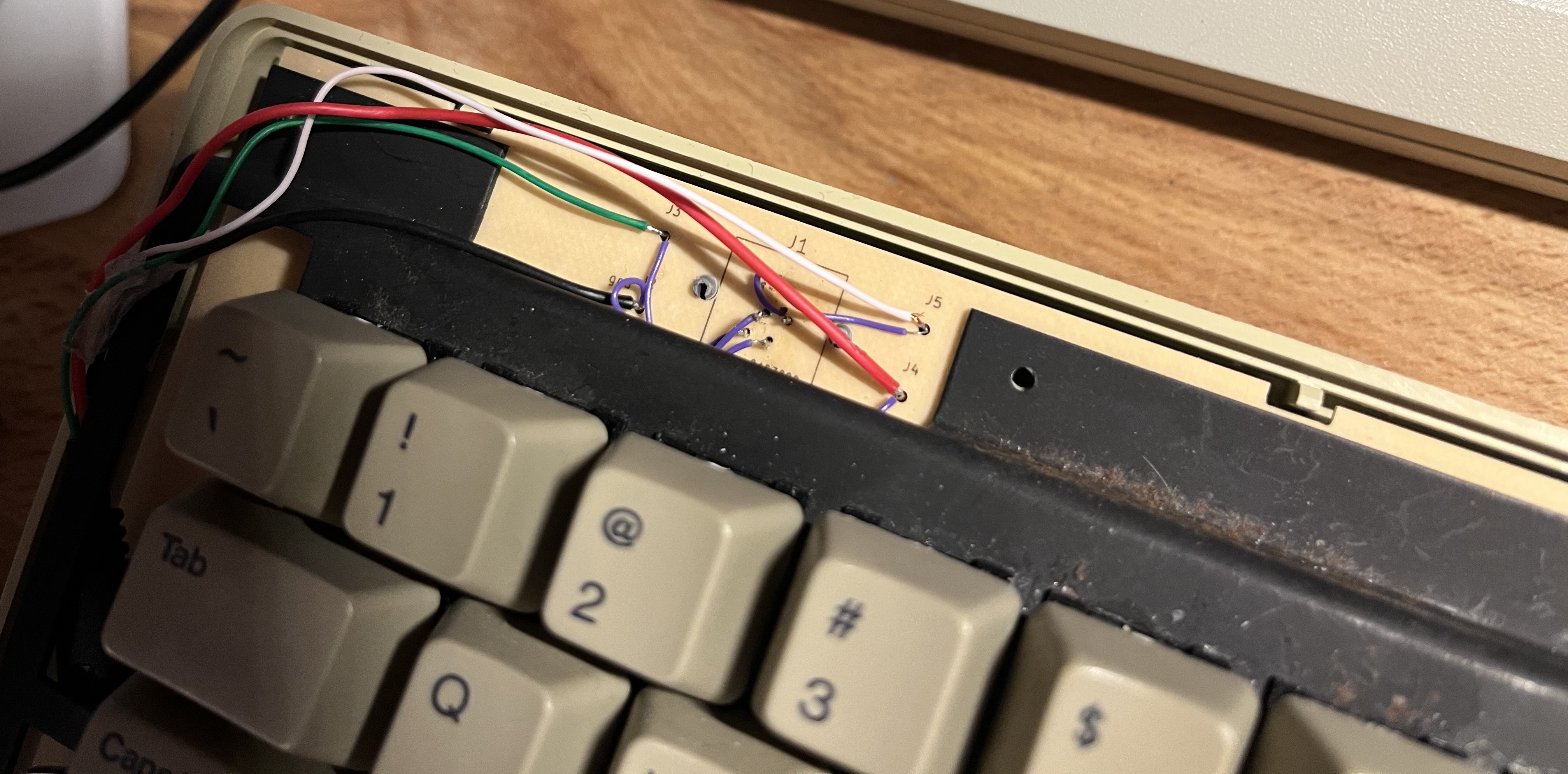
This is the hardest bit - put a small dab of solder on each pin of the 4p4c connector, then let it cool - then heat it up again and push the kynar wire into it. Once you've done this, you should have a connection from each pin on the micro side of your USB cable to the pins on the 4p4c connector, and you can continue to follow the rest of the cabling guide.